
This incinerator with “PYROLYTIC” combustion must have:
15. A combustion chamber of waste:
* Perfectly tight door for the manual loading of waste.The loading should be Manual, Batch Load,
* A burner of lighting which the use is limited to the ignition of waste.
* Top Loading loading with door seals gone up on hinges, wheel of screw plug, flexible joint, and stuffing insulating out of refractory.
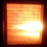
* The insulation of the combustion chamber should be composed of refractory bricks, having a high content of aluminum and insulates bricks in order to assure a minimum temperature on the outside sheet metal.
* Composition of the refractory;
Refractory concrete :
. Thickness : ≥100 mm
. Nature: 42% of Al203
Insulate in fibrous panels :
. Thickness: ≥75 mm
Nature: Calcium silicate.
* Burner of lighting of waste, with fuel, standard mono-bloc casting guiding plunging flame, lighting and safety of electronic ignition, permanent ventilation, electromagnetic sluice gate of regulation and isolating valve.
* Plate of combustion in Carborundum, avoiding the fixing of glass and slags.
16. Load Method: Top Loading
17. A chamber of post combustion of gases
* A burner of combustion of gases,
* A device of injection of air allowing a total recombustion of gases,
* A device of air inlet of cooling of waste gases,
* A sheath of evacuation of the gases burnt.
* Carcass in strong sheet steel with support of connection.
* Composition of the refractory;
Refractory concrete :
Thickness : ≥180 mm
Nature: 65% of Al203
Insulate in fibrous panel :
Thickness: ≥85 mm
Nature: Calcium
* Burner with fuel, mono-bloc casting guiding type with horizontal flame, lighting and safety of electronic ignition, permanent ventilation, electromagnetic sluice gate of regulation and isolating valve.
* A secondary injection of air to ensure perfect oxygen content.
18. A control box ensuring the complete cycle of combustion.
19. Fan:
* Electro-ventilator distributing the secondary air, the regulation of the air flow being carried out by valves and following the control of the automatic cycle.
20. Controls and regulations:
Control box water tight to dust, including:
* A switch circuit breaker for each engine (ventilators and burners).
* A timer with adjustable temporization for the regulation of each burner.
* A regulator with digital watching for the temperature of combustion.
* A regulator with digital watching for the temperature of postcombustion.
* Electric box.
21. The de- ashing must be done in the bottom of the combustion chamber or the deashing should be Automatic or manual batch de ashing.
22. Process Filtering system: Scruber to be mentioned as optional
23. Emission Standards Compliance: BS 3316 or equivalent standard
24. Capacity to treat Plastic:Not less than 40% by weight
25. CE Manufacturing Compliance’s EN 746-2-1997
26. The supplier must give batches of spare parts of first urgency and consumable of the incinerator.
27. The installed incinerator must bear a two years guarantee.
28. The supplier shall perform an onsite installation of the incinerator.
29. The technical training of operators will have to be provided and given by a technician from
the factory; it will consist of curative and preventive maintenance, and the use of machine, etc
30. Fence Wire around Incinerator (Chain Link):
(i) Should be NOT less than 2.5 Meters Height
(ii) With Concrete Foundation of 0.5 Meter Height
(iii) Secured with two Double Door (Grill Gates) fixed in different sides of the Fence
(iv) One of the Double Door (Grill Gate) should be fixed with Small Single Grill Door (2.5ʹ Width & 6ʹ Height)
(v) Double Door (Grill Gate) should be Not less than three (3) Meters Width


